Nametag
Sketching, Extruding, Text, Fillet
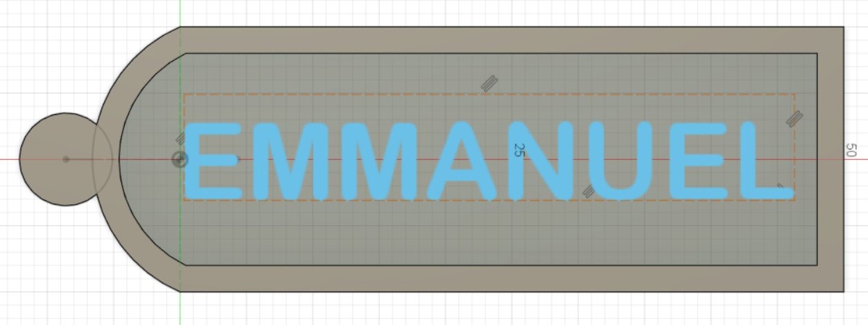
- Create a sketch and used a rectangle, an arc and a circle to create the shape of the nametag.
- Include the relevant dimensions of the nametag before using the command Extrude to turn the sketch into a 3 dimensional body by creating a height to the nametag. I extruded the edge by main body by 2mm, and the edge by 3mm.
- Creat a hole for the key ring of diameter 2.5mm.
- Creat another sketch to put my name in using the Create Text function to put my name before extruding it by 1mm.
- Round off the corners using the Fillet command by 2mm for the outer corner, and 1mm for the inner corner.
Fidget Spinner
Revolve, Pattern. Houses a ABEC 608 Bearing and 3 M8 stainless steel hex nuts.
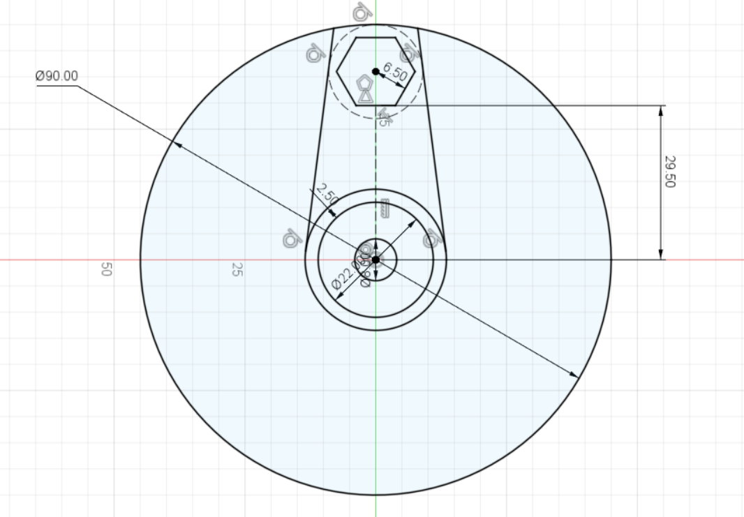
- Start with a sketch with a circle of diameter 40mm as a limit to how big the fidget spinner is, before designing one arm of the fidget spinner using a hexagon to house the nut, a circle for the centre, and 2 lines tangent to the circle for the arm.
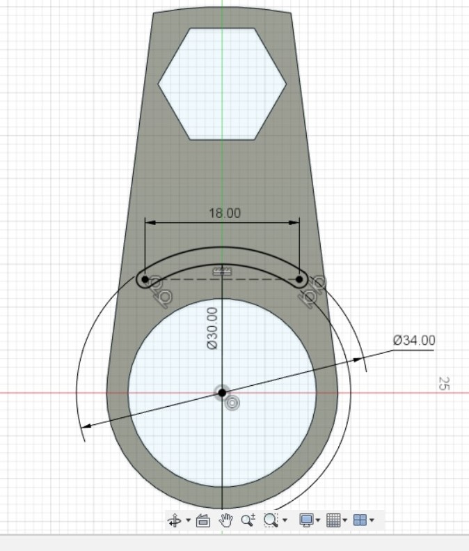
- Extrude one arm by 8mm
- Create a groove for aesthetics and fillet the inner radius.
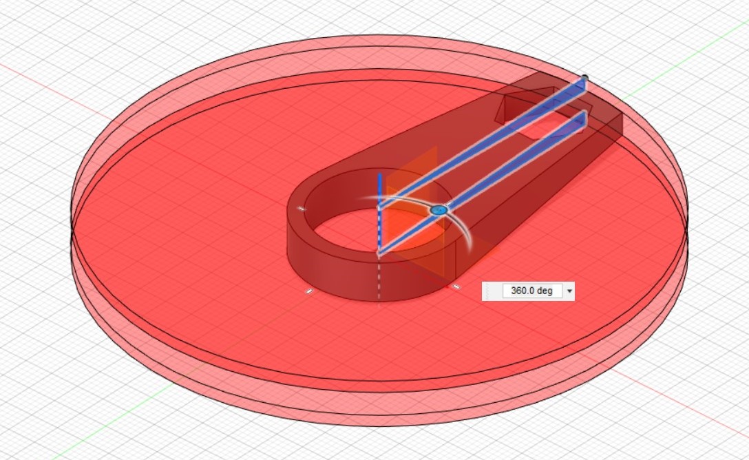
- Create another sketch for a taper in the arm and revolve cut the arm about the Z axie
- Use Pattern - Circular to duplicate the arm 2 more times around an the Z-axis and combined the 3 different arms together as one body
- Fillet of 12mm between the 3 arms.
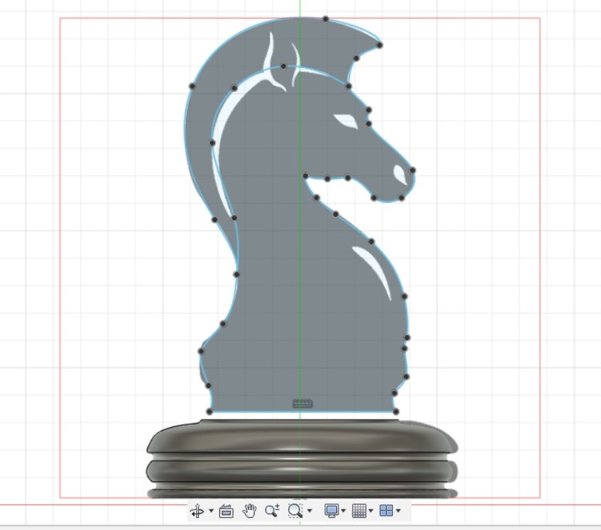
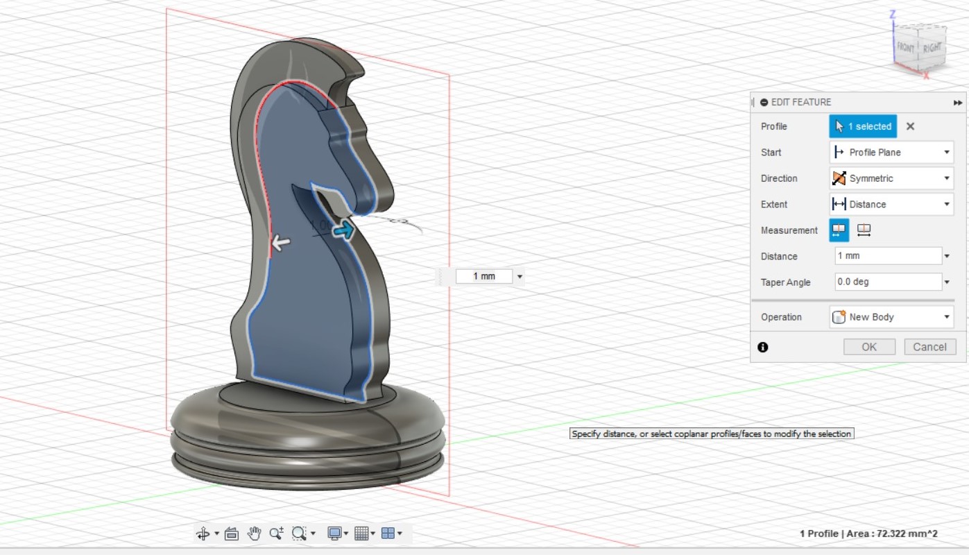
Knight Chess Piece
Canvas, Fit Point Spline tool.
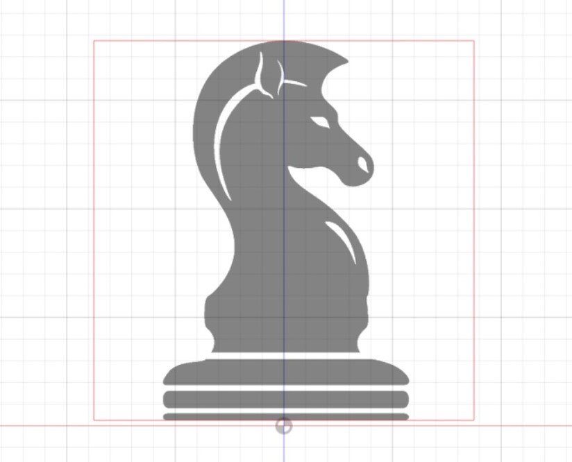
- Start by importing an image of a Knight Chess piece into Fusion.
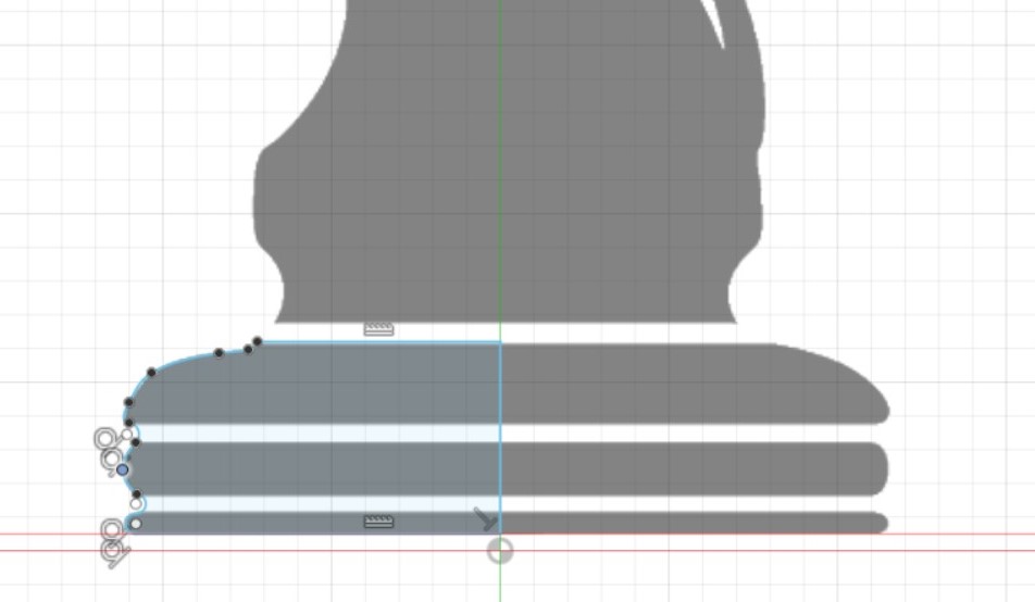
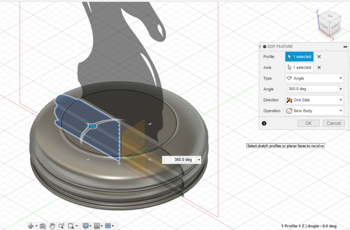
- Start a sketch to model the base. I used the Line tool and Fit Point Spline tool to model one half of the base before revolving it
- Create a sketch with the shape of the horse using the Fit Point Spline Tool. I then extrude the body of the horse by 1mm with a Symmetric direction, and the mane of the horse by 0.5mm.

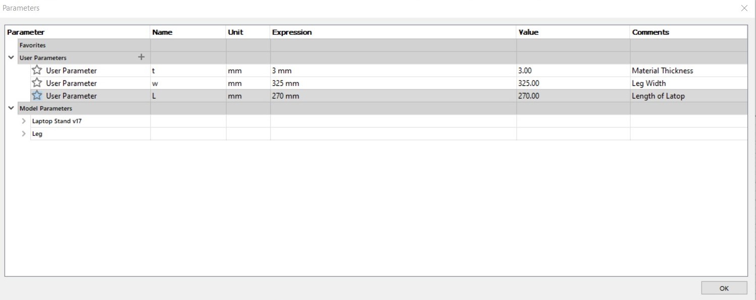
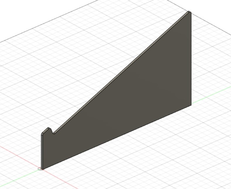
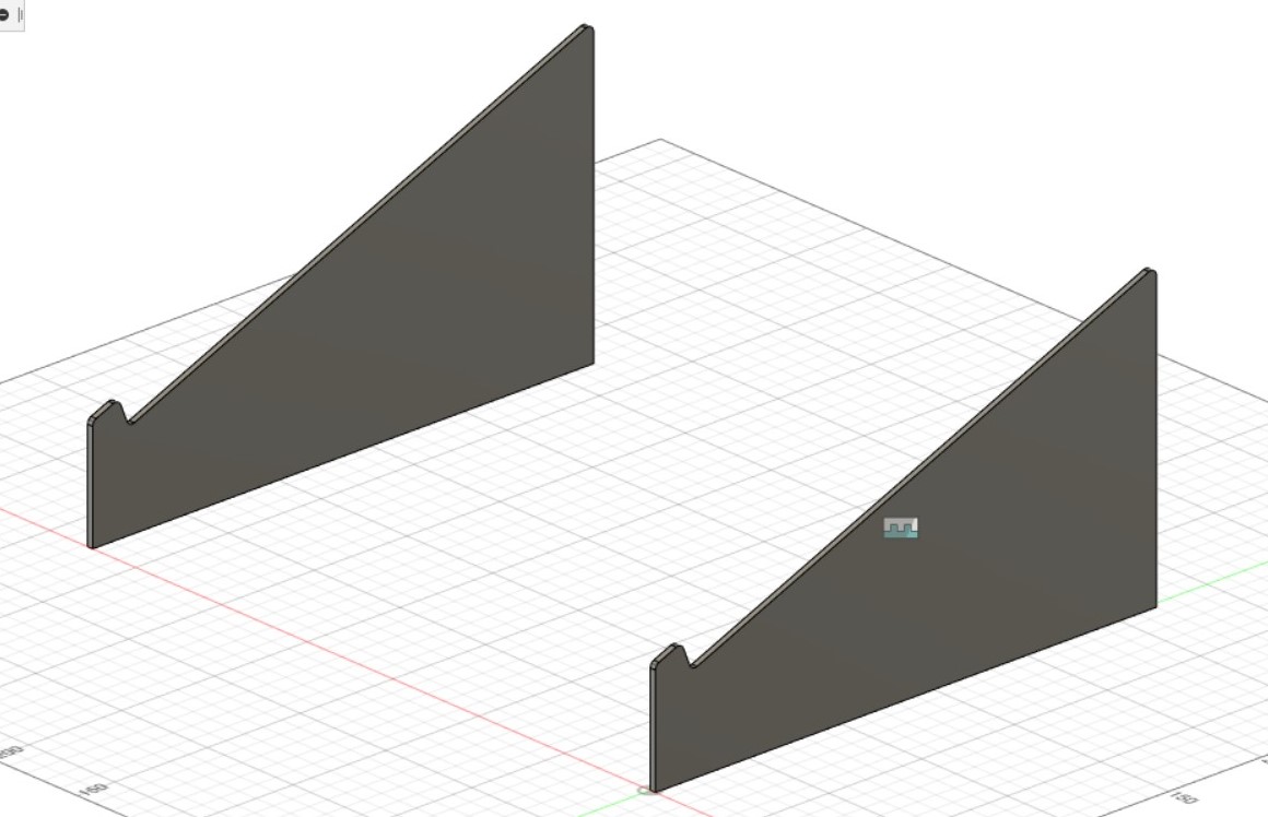
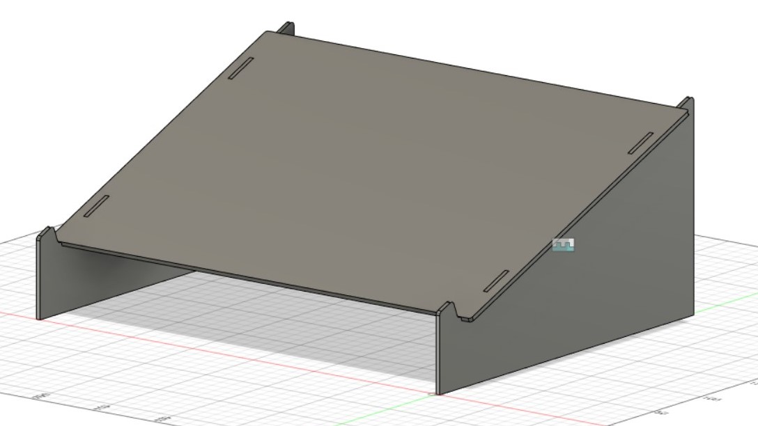
Laptop Stand
Components, Parametric Modelling.
- Start by inputting the User parameters such as the material thickness, length and width.
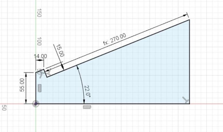
- Create a new component called "Leg" and started a sketch with the following dimensions.
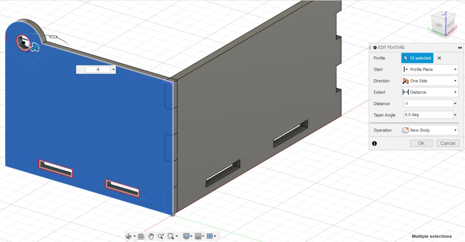
- Extrude the sketch of the leg by "t" which is the user parameter for the thickness of the leg
- Copy and paste the component "Leg" to create the second one. Joint the 2 surfaces of the 2 legs, and specify the offset by 325mm. Fillet the top edges by 3mm to round the sharp edges.
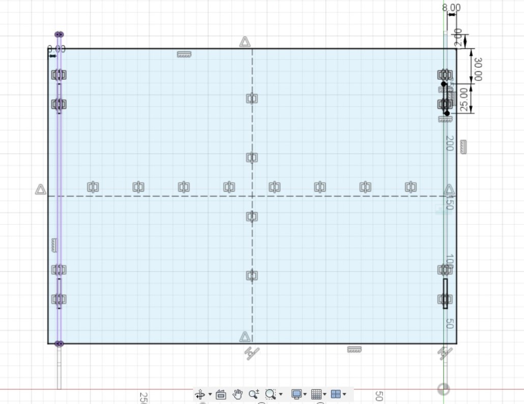
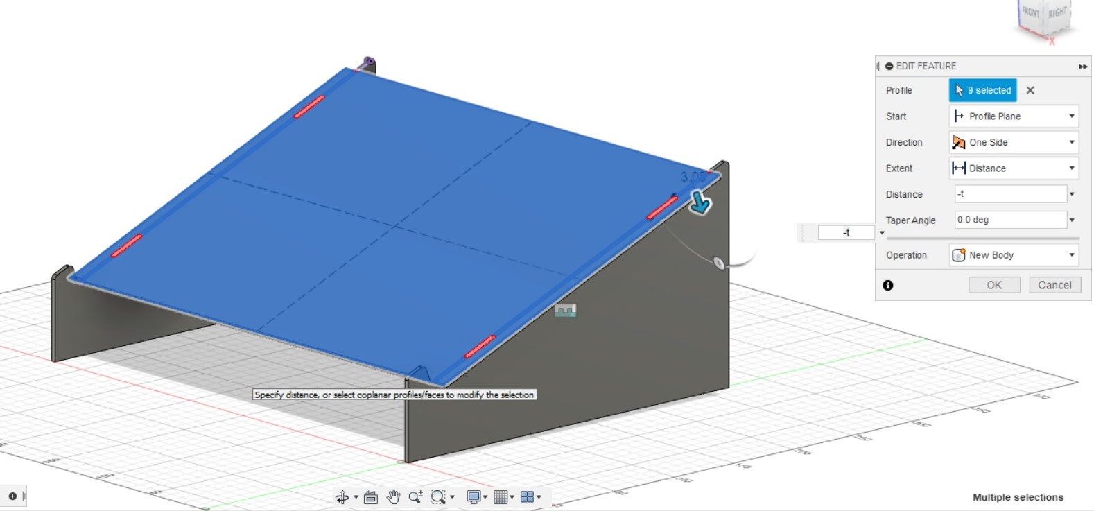
- Create a new component "Top" and start a sketch on the top surface of the original leg by creating a rectangle.. In order to secure the top onto the legs, we would use 4 rectangular holes in the top and 4 tabs in the leg. Create 4 smaller slots as holes for the tabs to go through.
- Extrude the top by the material thickness downwards into the legs. (ensure that the 4 rectangular holes are not selected)
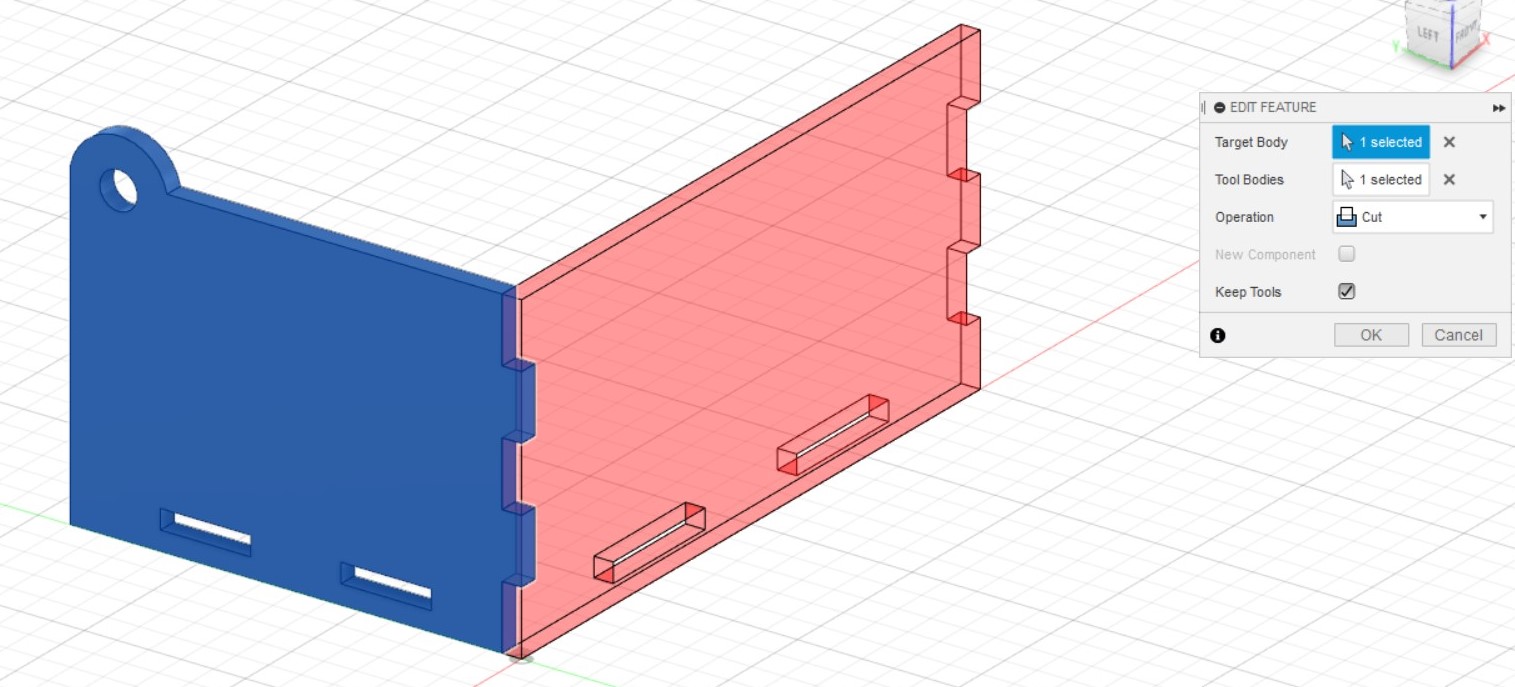
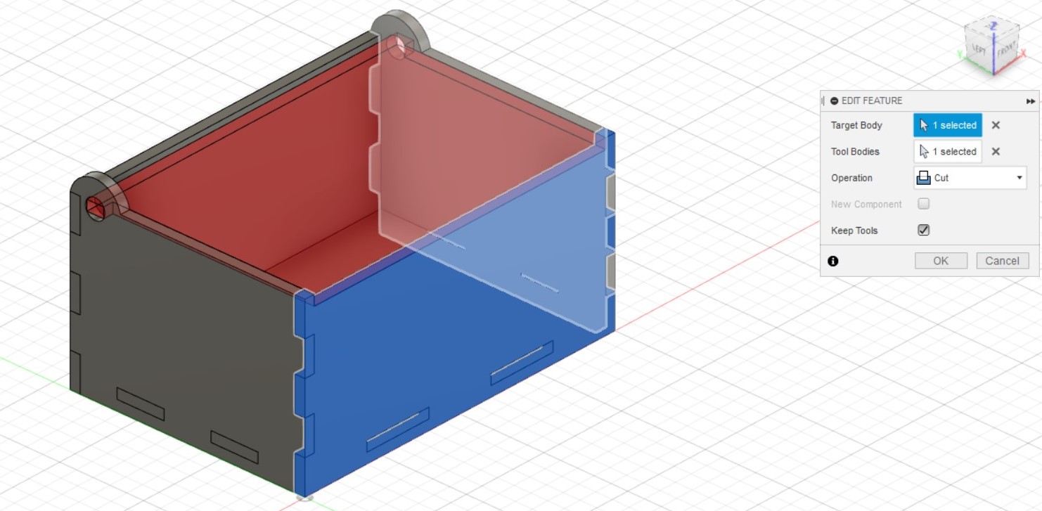
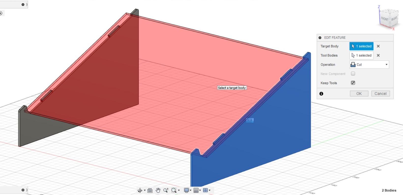
- To create the tabs in the legs and remove material of the leg that intersects the top, use the combine function. Select the original leg as the target body (the component you are changing) and the top as the tool body (the component you are using to change the target body). Use the "Cut" operation and check the box which says "Keep Tools". Since the 2nd leg is a copy of the first leg, the changes made to the 1st leg will also be reflected into the 2nd one. Fillet the external corners by 2mm, and the corners of the tabs on the legs by 0.5mm
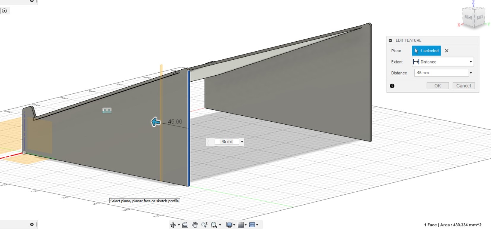
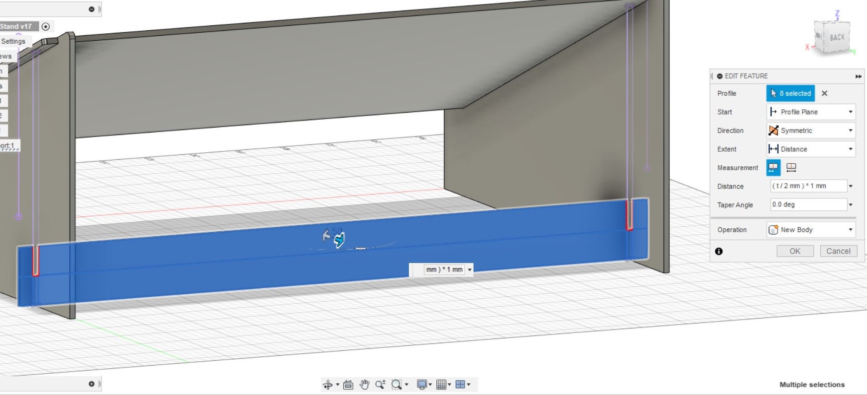
- Create a new component "Support" and a new plane where we would sketch our support. The plane is created by Offset from the back of the leg by a distance of 45mm
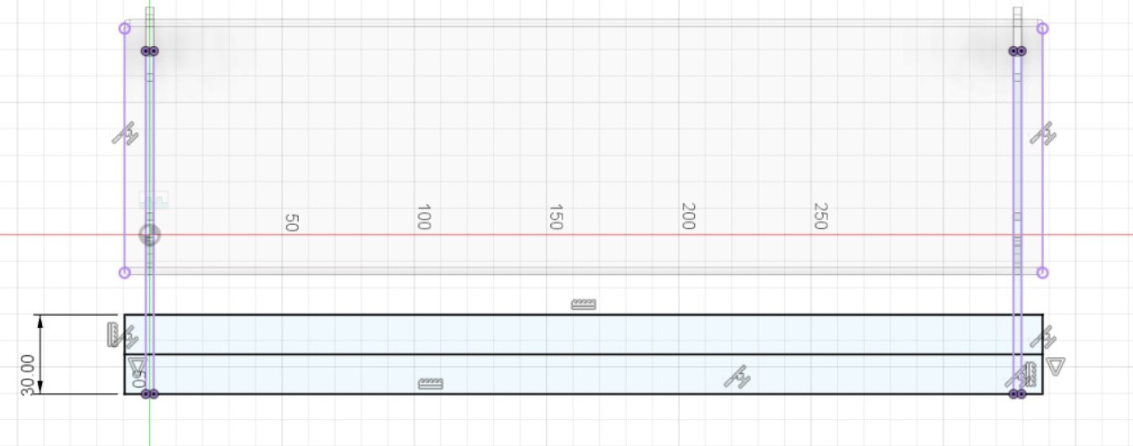
- Create a rectangle and dimension it. Draw a horizontal line to divide the rectangle into 2 equal piece. This will help create 2 rectangle at the top half of the support that will serve as slots to fit the support into the legs.
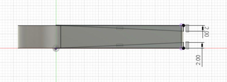
- Extrude the support symmetrically (extrudes the sketch both side) by the "t/2", which is half of the thickness of the material. Ensure that you do not select the 2 small rectangles that will serve as tabs.
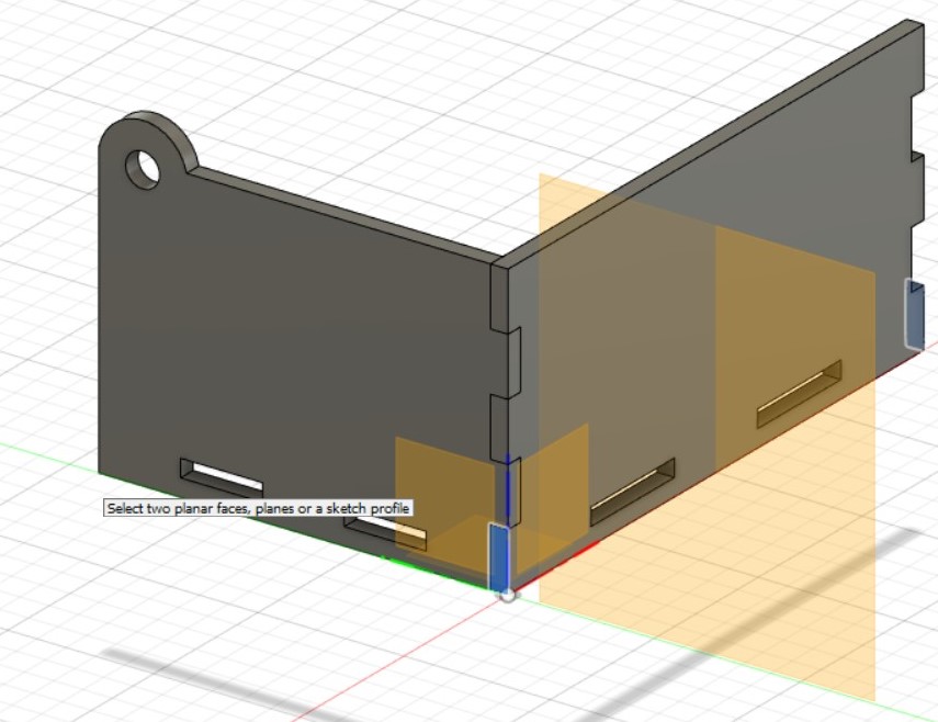
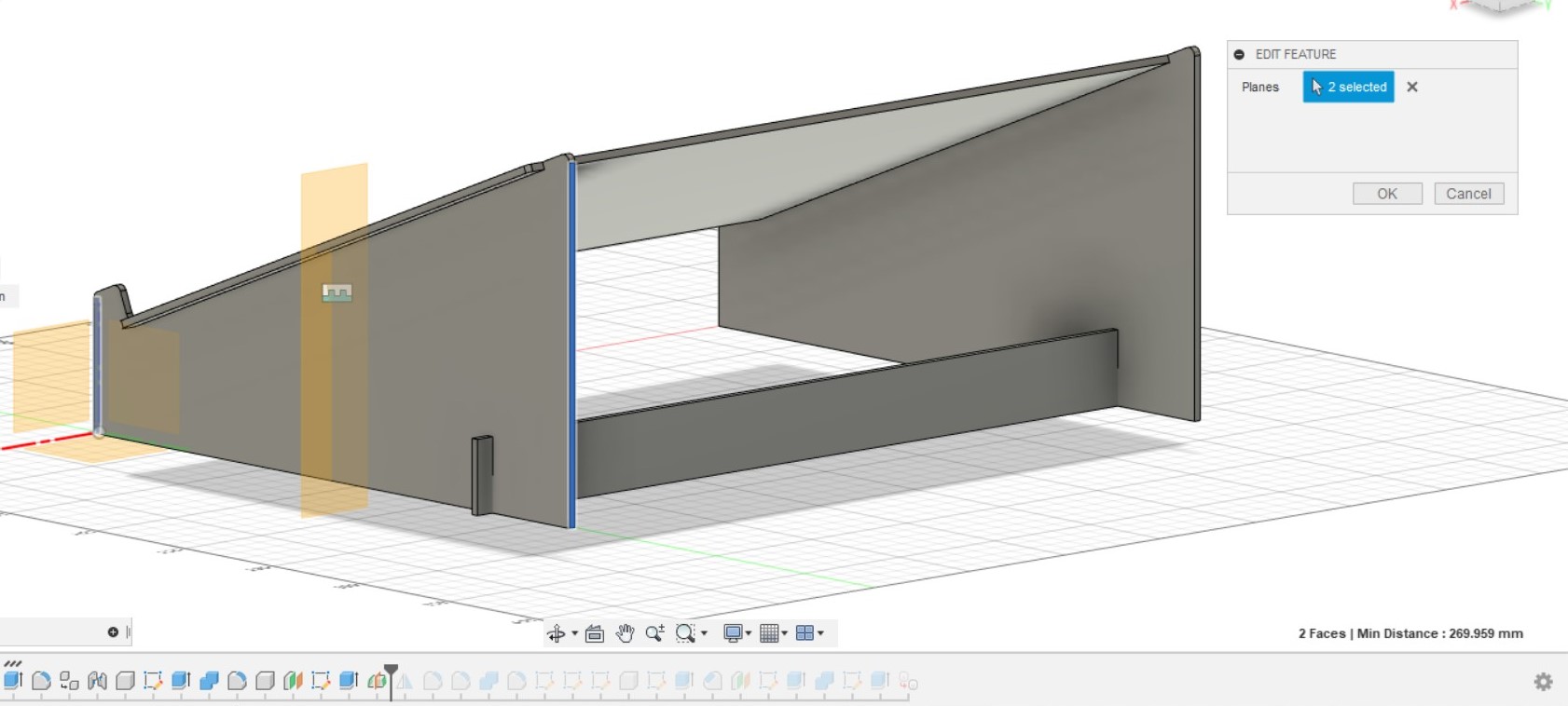
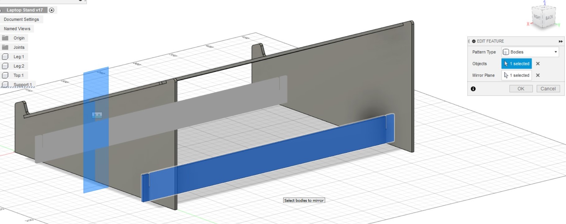
- To create the 2nd support, we will create a new plane that will serve as a mirror plane to mirror the original support. Construct a midplane and select the front and the back of the leg to create a plane in the middle of the leg
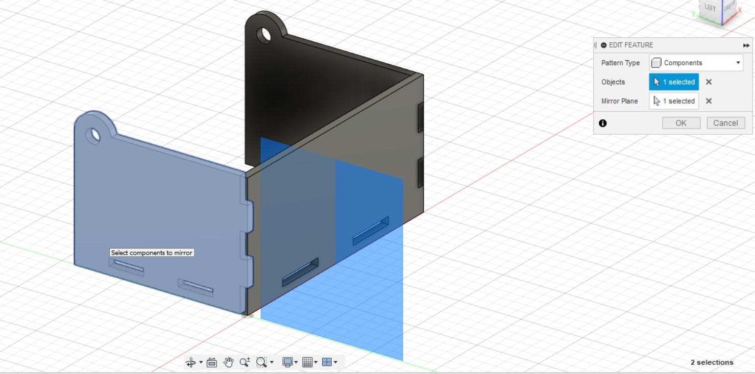
- Create > Mirror the body: Support and use the previously constructed midplane as a mirror plane. Fillet the corners by 2mm
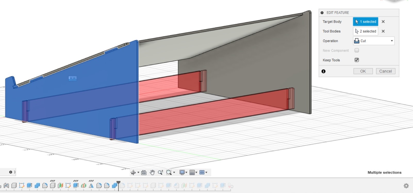
- To create the slots in the legs, use the combine function. Select the original leg as the target body and the 2 support as the tool body. Use "cut" operation and check the box "Keep Tools. Fillet the internal corners of the slots by 0.5mm to make sliding the support into the legs easier.
- To show how my laptop would look like on the stand, I created a new component and used sketch, champfer and extrude to model my laptop with the same dimensions before animating the construction of the laptop stand
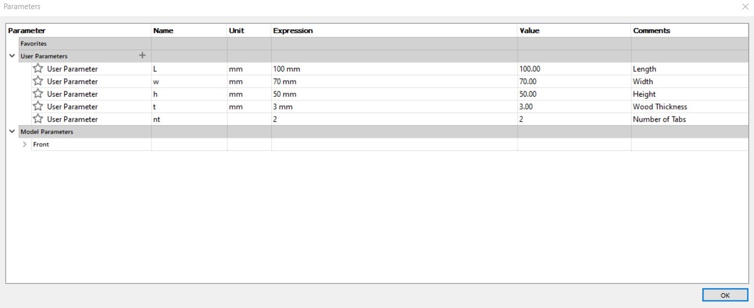
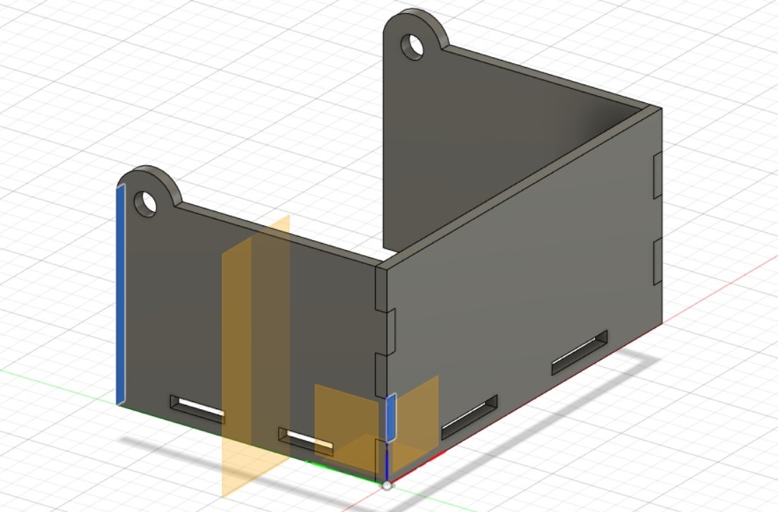
Box
Components, Parametric Modelling.
- Start by inputting user parameters: Thickness of material, length, width and height of box, number of tabs
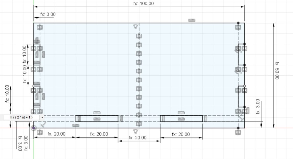
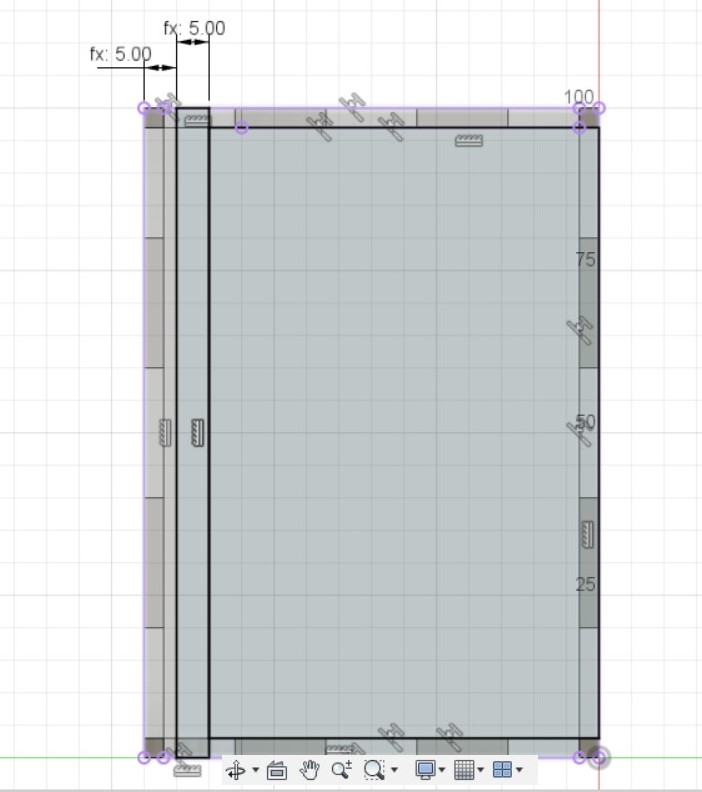
- Create a new component named "Front" and create a new sketch in that component. Make the basic shape of the front by creating a rectangle, and input the dimensions of the rectangle with the parameters "Length" and "Height". Create 6 rectangles that will serve as holes to connect the front to the sides and base using tabs. The width of the rectangles is the thickness of material, and the height for the 4 side tabs is (height / (2 * numberoftabs + 1)), and the 2 bottom tabs is (length / (2 * numberoftabs + 1)). You can create 2 rectangles on one side, create a vertical construction line that splits the rectangle into half, and mirror the 2 rectangles to the other side using the construction line as a mirror line.
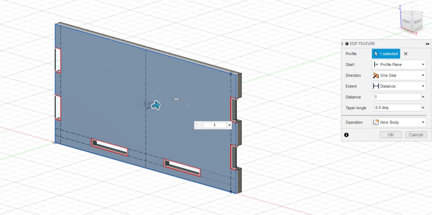
- Extrude the front by the thickness of the material, excluding the 6 rectangles.
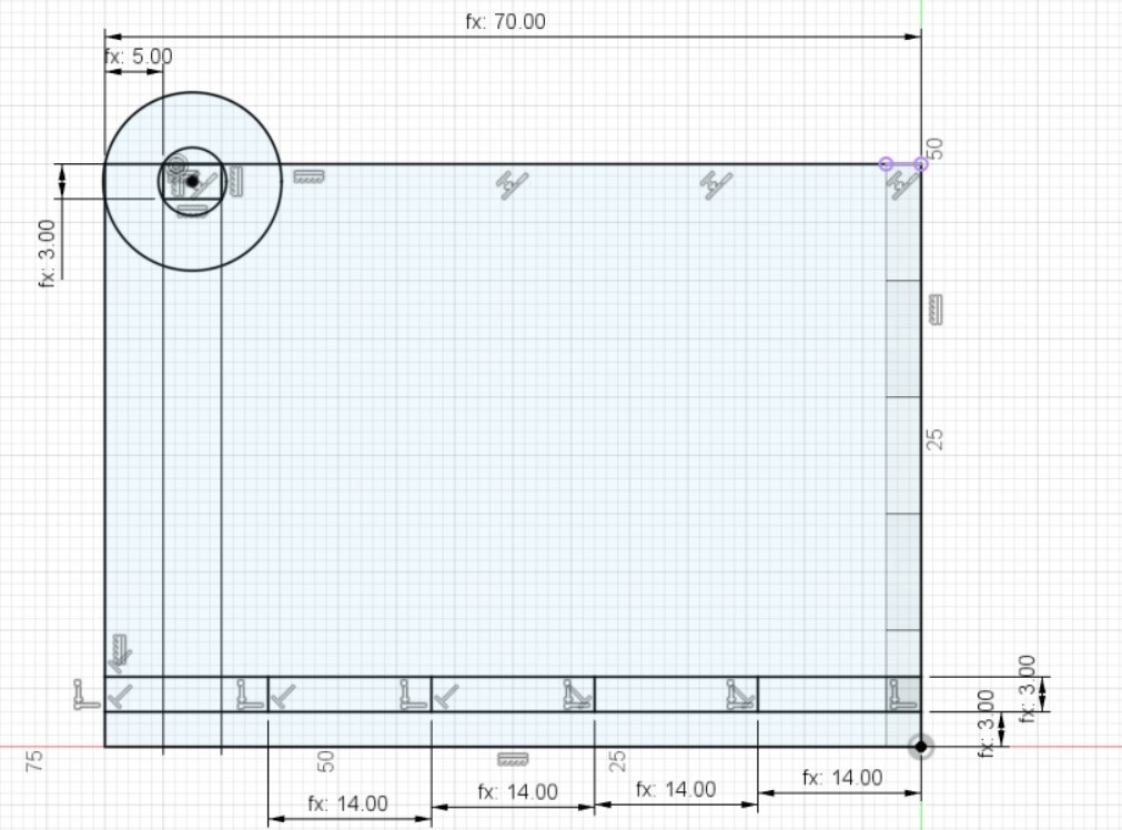
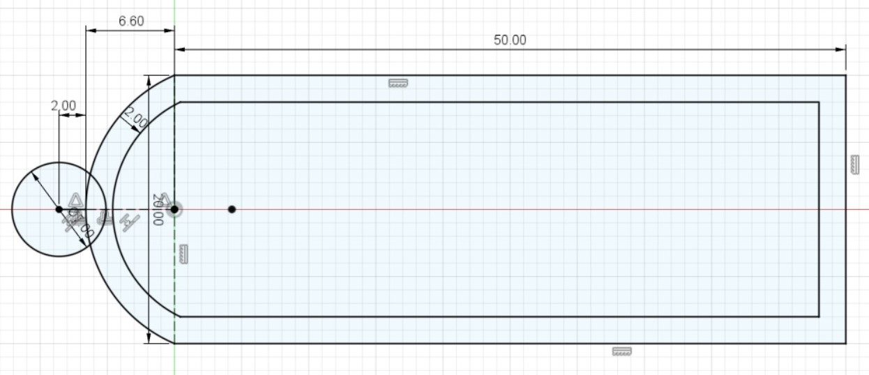
- Create a new component "Left". Start a sketch with a rectangle with dimensions of user parameter "Width" and "Height". Create the 2 holes for the base, and you can do so by using lines instead of rectangles. (The 2nd and 4th rectangle would be the holes.) I also intend to create a hole for the lid to revolve around. Start with a rectangle that represents the lid's axis, and how it would be relative to the side of the box. The width of the rectangle is "t" and the length is "5/3 * thickness". I then create a circle around that rectangle, and another larger circle with the centre coincident to the smaller one. To constrain the position of these 3 objects, the rectangle top edge is collinear with the top of the side of the box, the larger circle circumference is coincident to the top left corner of the side of the box, and the distance of the small rectangle to the left edge of the side of the box is (5/3 * thickness)
- Extrude the side of the box by thickness, excluding the hole for the lid and the 2 small rectangle.
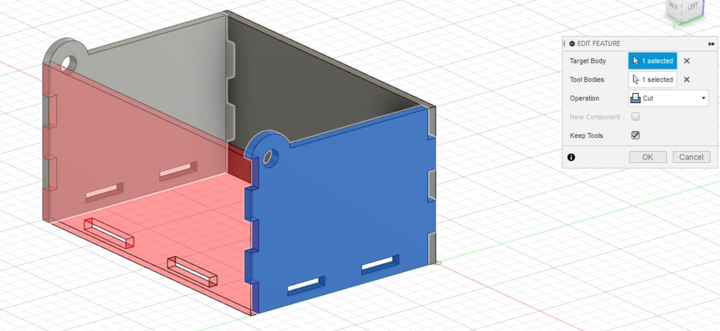
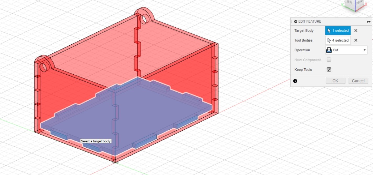
- Remove the overlapping material from the front and side by using the combine function. Select the side as the target body and the front as the tool body, operation cut and keep tools.
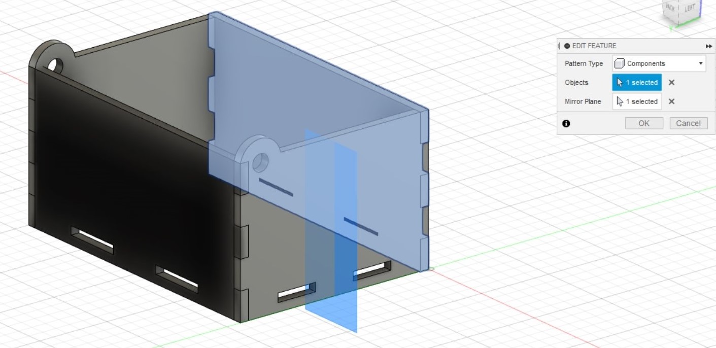
- To mirror the left side to the right, first create a midplane that will be used as a mirror plane. Select the 2 edges of the front side to be used to construct the midplane. Create > Mirror the left side about the new midplane, Pattern type: Component, to make a new component. You can rename this mirrored component "Right" after mirroring.
- Repeat the previous step to create the back side of the box by making a new midplane and mirroring the front side.
- Remove the overlapping material from the 2 sides and the back by using the combine function. Select the left side as the target body and the back as the tool body, operation cut and keep tools. Use the combine function again for the right side
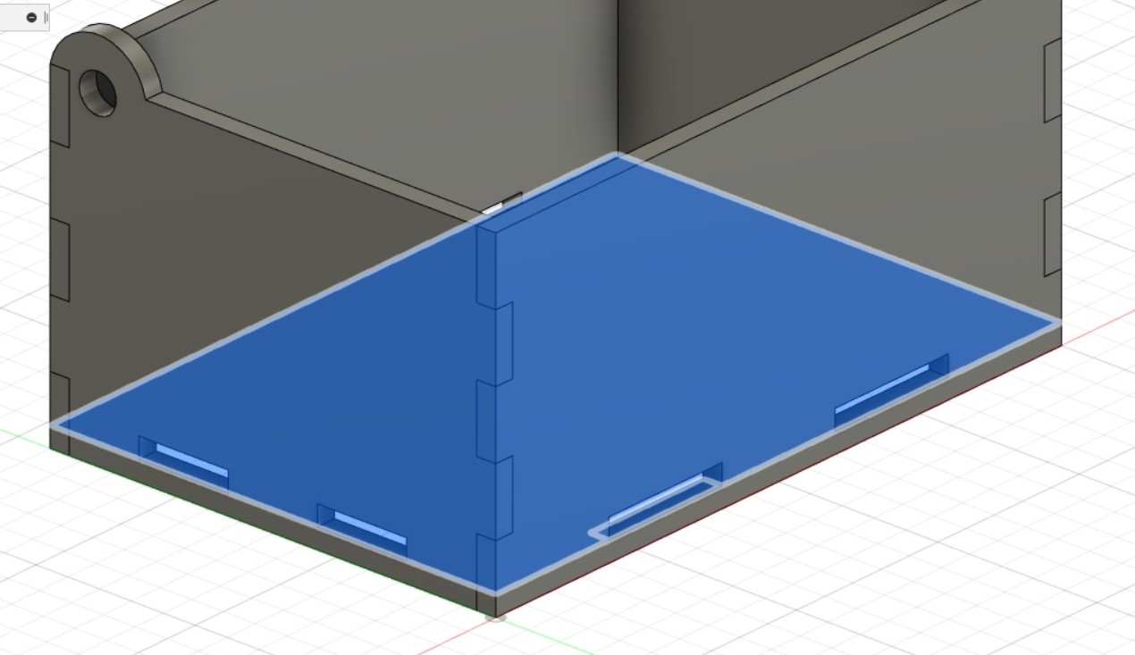
- Create a new component "Base" and start a sketch on the bottom of one of the holes. Create a rectangle of length with user parameter "Length" and width "Width". Extrude it upwards by the parameter thickness
- Remove the overlapping material from the base by using the combine function. Select the base as the target body and the front , side and back as the tool body, operation cut and keep tools.
- Create a new component "Lid". Since the lid would be flush with the top surface of the sides of the box, you can start a sketch on one of the top surface. Create 2 rectangle, one long narrow one as the axle, and another larger one as the lid. Apply collinear constraints and dimensions similar to that when we created the hole in the side of the box for the lid. Extrude it downwards by the thickness.
- For the lid to fit snugly on the front side of the box, use the combine function to remove material from the front side. Select the front as the target body and the lid as the tool body, operation cut and keep tools.